Nutrient Film Technique
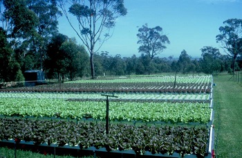
The main components of NFT systems are the growing channels, the benches or supports which hold the channels if they are to be raised above the ground (typically for lettuce, herbs and smaller plants), the main nutrient tank, the nutrient delivery systems and the return channels.
NFT channels must be constructed from `food safe’ plastics as toxic compounds can leach from certain plastics into the nutrient solution and become a concern both for plant growth and the safety for consumers of the produce grown. There are a wide range specifically designed rigid NFT channels on the hydroponic market, most are rectangular in shape, however oval channels and composite channels with clip off lids are available. While buying pre made channels may be capital intensive, the major advantage is these systems also provide ready to fit end caps and other fittings required to create a leak proof system.
NFT channels can also be constructed from other materials on side – rigid PVC downpipe, water pipes and drainage pipes can be used to create NFT systems provided they are made from `food safe’ materials, however preference should be given to larger, rectangular profile channels and materials rather than round pipes. Other materials that can be used are concrete or timber formed channels, lined with polythene film, a double layer of film is recommended as leaks can occur over time. For larger crops such as tomatoes, heavy gauge polythene film (such as the black and white `panda film’) can be formed into triangular gullies on a flat and level surface. These film channels are inexpensive to install, however they are prone to major leaks and the film must be securely clipped to a wire to hold the shape of the channel as plants develop.
Metal should not be used for NFT channels, unless it is completely lined with polythene film or coated with a non toxic covering. Many metals react with the nutrient solution both corroding the metal and releasing unwanted elements into the plants root zone.
NFT channels sited at ground level may require some additional support beneath the channel to ensure it stays flat and at the correct slope.
Channels raised up to a good working height can be supported by frames of galvanised pipe, timber or metal benches or any other support with is stable and at the correct slope to allow the nutrient to flow correctly.
Sensors can also be included to measure levels of electrical conductivity (EC) and pH. The EC can be increased through automatic injections of nutrient stock or concentrate solutions triggered by sensor readings. Injections of potassium hydroxide are used to increase the pH reading (raise the alkalinity), and injections of phosphoric, or nitric acids can be used to lower pH readings (make it more acid).
Water chillers can also be installed to reduce water temperatures of solutions during hot conditions. These also oxygenate solutions and circulate them in addition to chilling. Those with stainless steel drive shafts are better in nutrient solutions.
NFT Channel Size and Solution Volume
The main objective in determining the length, width and slope of NFT channels are to ensure they are large enough to hold the root system of the crop, no ponding occurs and that the solution flows at a constant rate down each channel. Channels should be constructed of sufficiently rigid material, or be well enough supported that their slope and cross section remain constant along their entire length.
One litre of nutrient solution is enough to provide a 2mm deep film, 100mm wide and 5 m long at zero slope. For a channel 20m long therefore, a 1 litre/minute flow of nutrient solution will take four minutes to produce the required depth across the entire surface of the channel. That is, a 20 long channel, 100mm wide with a solution depth of 2mm, will hold four litres of solution. Using this example it is easy to calculate the solution volumes and flow rates required in a standard NFT system. Other factors such as the cohesive properties of nutrient solutions to the channel base and sides, the tendency of solutions to flow in `trickles’ rather than complete films, the effect of channel slope, curvature and flow from the ends complicate the calculation of solution flow and depths in an NFT channel.
However the following simple formulae can be used to obtain a good guide to system requirements:
Volume in channel at 0 slope (V) litres = 1000 x L x W x D (m)
Where:
L is the length (meters)
W is the width (meters)
D is the depth (meters) of solution in the gully
Nutrient `turnaround’ at 0 slope (minutes) = F/V
Where:
F is the flow rate in litres per minute
V is the volume of the channel in litres
And solution Velocity (meters/minute) = flow (m3/minute)/cross sectional area (m2)
NFT Channel Slope

The slope of the NFT channels will determine the effect of flow rate on solution depth, due to its influence on solution velocity. A higher slope will allow a greater volume of water to flow at a shallow depth while, conversely, reducing the slope of the channel will produce a greater depth of solution at a proportionally slower flow rate.
Therefore, steeply sloping channel will accommodate a higher flow rate while maintaining a shallow depth of film and so produce better oxygenation of the nutrient solution. A less steeply sloping channel will require a lower flow rate to achieve this same result of a shallow depth and oxygenation and this is turn reduces the length of the channel in terms of the number of plants the reduced flow (and hence lower volume of oxygenated solution) can support. If longer channels are required, the slope and flow rate should be increased. The limits this places on physical access to the channels at the top end, also limits the channel length in NFT systems
NFT Delivery and Drainage
The delivery pipe and drainage gully should be selected to supply sufficient volume to and from each growing channel. The flow rate to be supplied by the delivery pipes can be calculated, by multiplying the flow rate into each channel by the number of channels.
The drainage gully can be treated as a channel using the formulate below, when considering the size, slope and cross section required to carry each volume of solution back from each set of channels to the nutrient tank.
You may also be interested in....